Principles of Operation
PRINCIPLES OF OPERATIONVehicle communication utilizes both medium and high speed controller area network (CAN) communications. CAN is a method for transferring data among distributed electronic modules via a serial data bus.
The vehicle is equipped with 2 module communication networks:
- Medium speed (MS) CAN
- High speed (HS) CAN
MS-CAN
The MS-CAN is a medium speed communication network that uses an unshielded twisted pair cable of data (+) and data (-) circuits. The data (+) and the data (-) circuits are each regulated to approximately 2.5 volts during neutral or rested network traffic. As bus messages are sent on the data (+) circuit, voltage is increased by approximately 1.0 volt. Inversely, the data (-) circuit is reduced by approximately 1.0 volt when a bus message is sent. Multiple bus messages can be sent over the network CAN circuits allowing multiple modules to communicate with each other. The MS-CAN network will not communicate while certain faults are present, but will operate with diminished performance with other faults present. The MS-CAN network may remain operational when 1 of the 2 termination resistors are not present.
The MS-CAN network operates at a maximum data transfer speed of 125 Kbps for bus messages and designed for general information transfer. The network will remain operational, but at a degraded level when certain circuit faults are present. The MS-CAN network may remain operational with only one termination resistor present.
The following modules are on the MS-CAN network:
- Smart junction box (SJB)
- Instrument cluster
- Audio unit
- THX(R) amplifier (if equipped)
- Satellite radio receiver (if equipped)
- Electronic automatic temperature control (EATC) module (if equipped)
- Dual automatic temperature control (DATC) module (if equipped)
- Driver seat module (DSM) (if equipped)
- Driver door module (DDM) (if equipped)
- Climate controlled seat module (if equipped)
MS-CAN Network Communication Fault Chart:
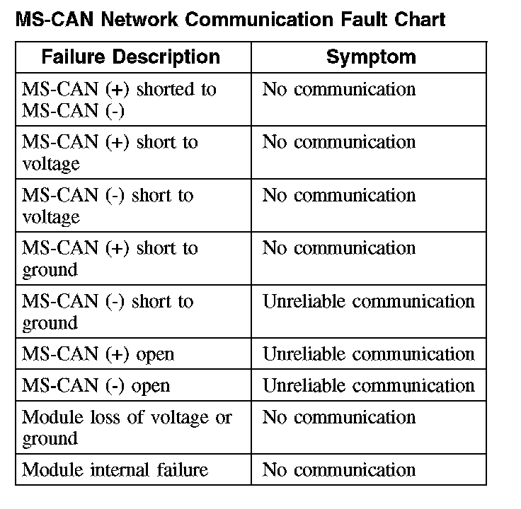
The fault chart describes the specific MS-CAN network failures and their resulting symptom.
HS-CAN
The HS-CAN is a high speed communication network that uses an unshielded twisted pair cable of data (+) and data (-) circuits. The data (+) and the data (-) circuits are each regulated to approximately 2.5 volts during neutral or rested network traffic. As bus messages are sent on the data (+) circuit, voltage is increased by approximately 1.0 volt. Inversely, the data (-) circuit is reduced by approximately 1.0 volt when a bus message is sent. Multiple bus messages can be sent over the network CAN circuits allowing multiple modules to communicate with each other. The HS-CAN network will not communicate while certain faults are present, but will operate with diminished performance with other faults present. The HS-CAN bus may remain operational when 1 of the 2 termination resistors are not present.
The HS-CAN network operates at a maximum data transfer speed of 500 Kbps and is designed for real time information transfer and control. The network will remain operational, but at a degraded level when certain circuit faults are present. The HS-CAN network may remain operational with only one termination resistor present.
The following modules are on the HS-CAN network:
- Powertrain control module (PCM)
- Transmission control module (TCM)
- Anti-lock brake system (ABS) module
- Restraints control module (RCM)
- Occupant classification sensor module
- Instrument cluster
- Four wheel drive (4WD) control module (if equipped)
HS-CAN Network Communication Fault Chart:
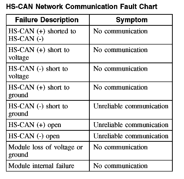
The fault chart describes the specific HS-CAN network failures and their resulting symptom.
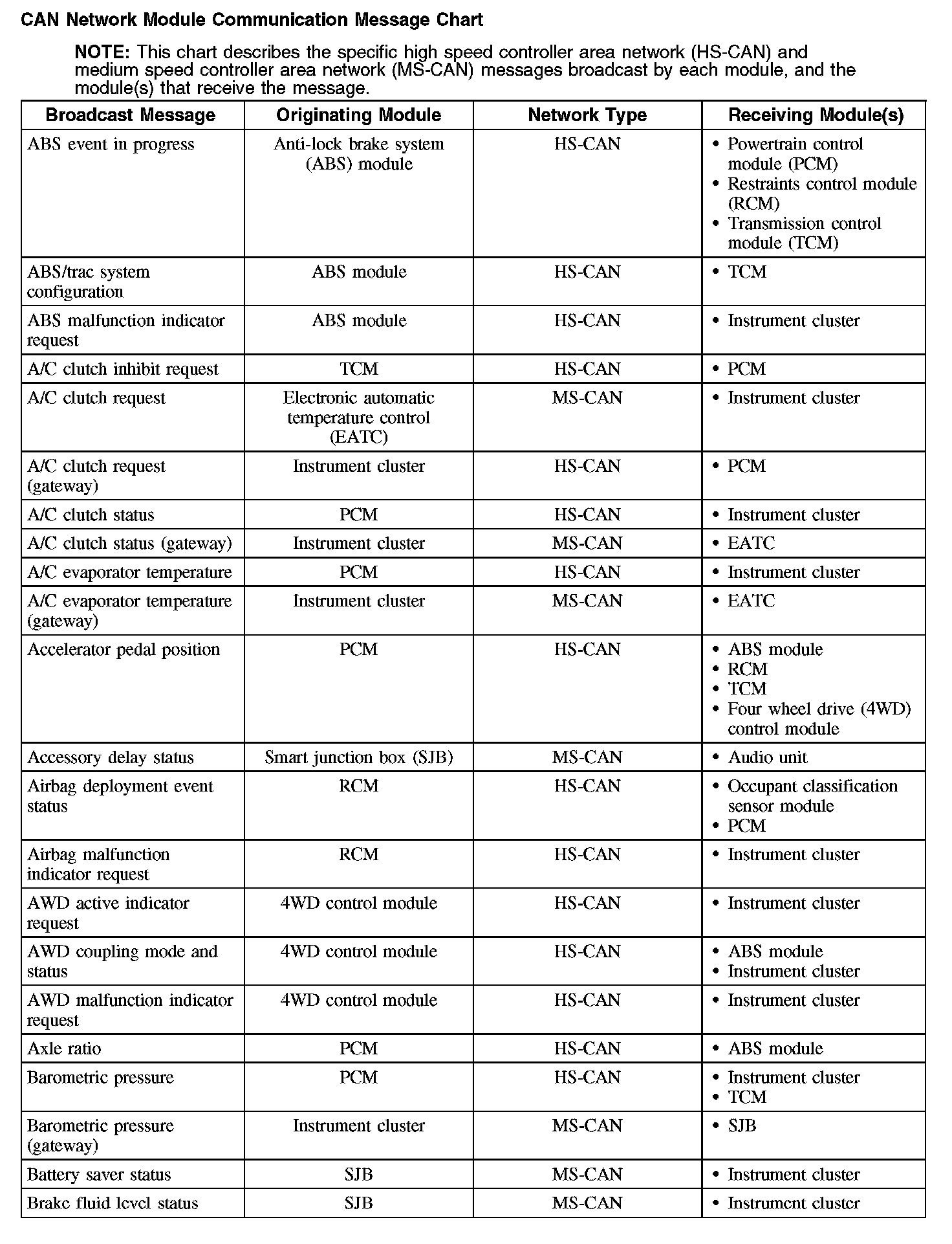
CAN Network Module Communication Message Chart (Part 1):
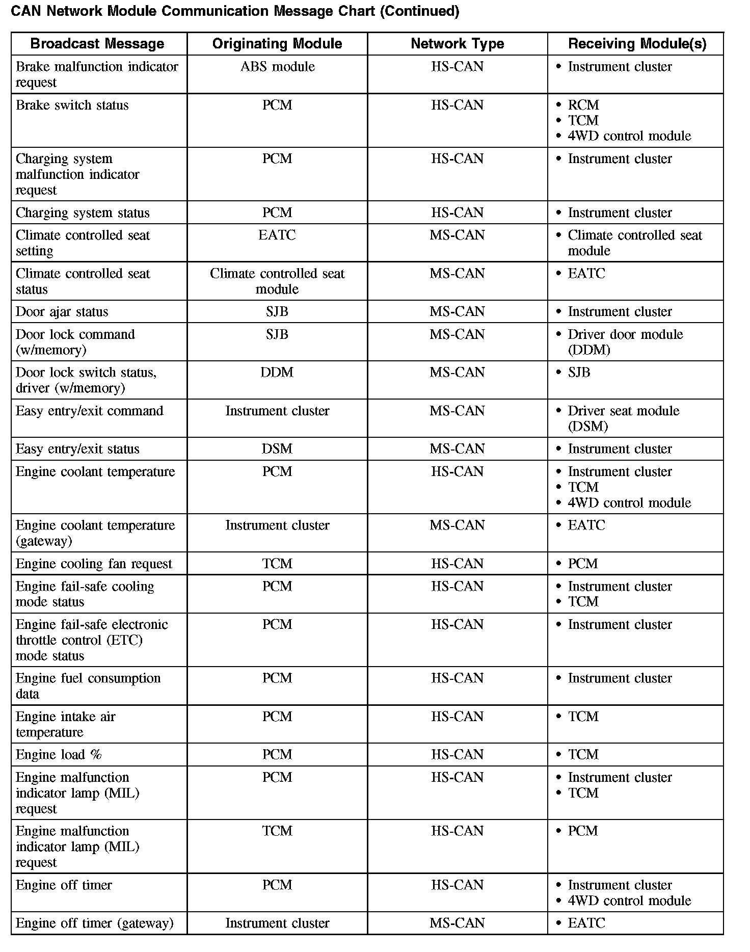
CAN Network Module Communication Message Chart (Part 2):
CAN Network Module Communication Message Chart (Part 3):
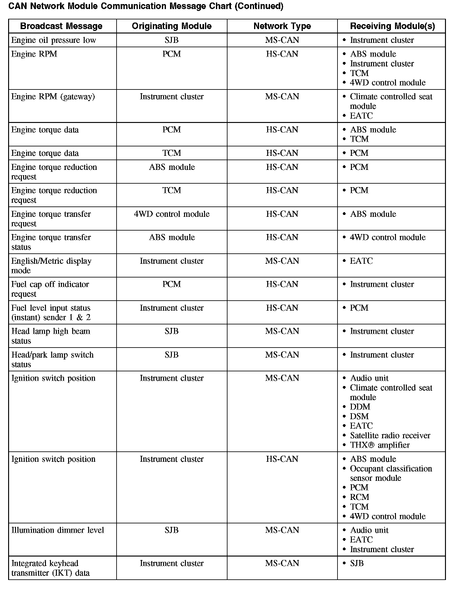
CAN Network Module Communication Message Chart (Part 4):
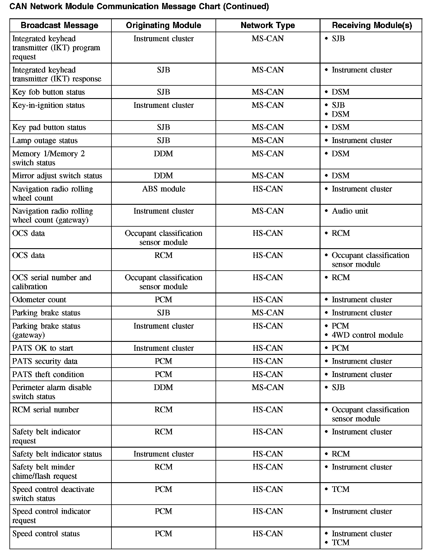
CAN Network Module Communication Message Chart (Part 5):
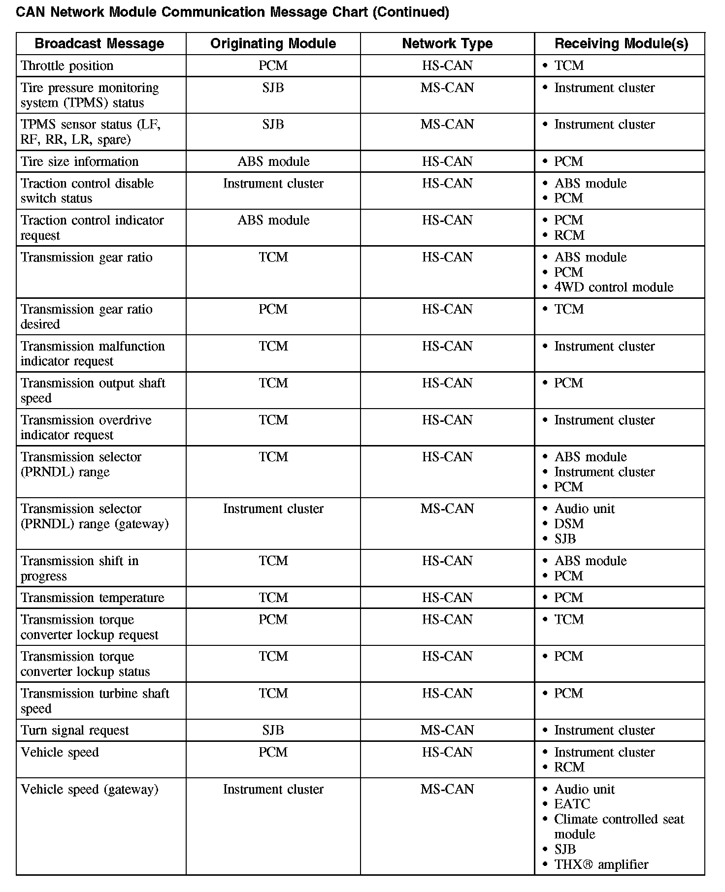
CAN Network Module Communication Message Chart (Part 6):
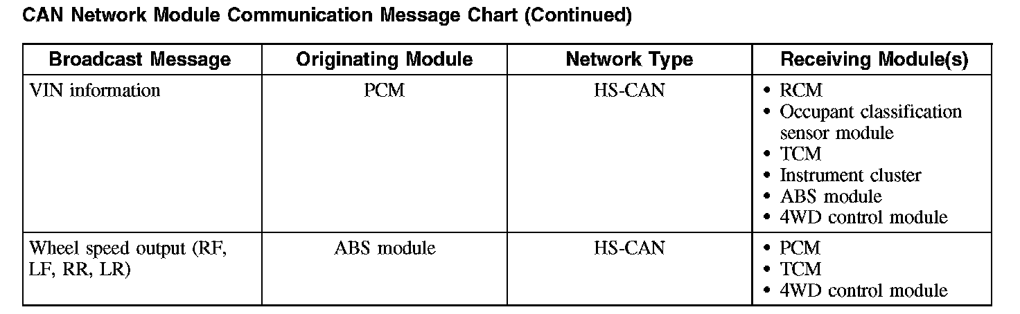
CAN Network Module Communication Message Chart