System Specifications
Cylinder BlockCylinder bore diameter - grade 1 90.200-90.210 mm (3.5512-3.5516 inch)
Cylinder bore diameter - grade 2 90.210-90.220 mm (3.5516-3.5520 inch)
Cylinder bore diameter - grade 3 90.220-90.230 mm (3.5520-3.5524 inch)
Cylinder bore maximum taper 0.006 mm (0.0002 inch)
Cylinder bore maximum out-of-round 0.020 mm (0.0008 inch)
Main bearing bore inside diameter 72.400-72.424 mm (2.850-2.851 inch)
Crankshaft
Main bearing journal diameter 67.481-67.505 mm (2.6567-2.6576 inch)
Main bearing journal maximum taper 0.004 mm (0.0002 inch)
Main bearing journal maximum out-of-round between cross sections 0.0075 mm (0.0003 inch)
Main bearing journal-to-cylinder block clearance 0.048-0.024 mm (0.0019-0.0009 inch)
Connecting rod journal diameter 53.003-52.983 mm (2.0867-2.0859 inch)
Connecting rod journal maximum taper 0.004 mm (0.0002 inch)
Connecting rod journal maximum out-of-round between cross sections 0.0075 mm (0.0003 inch)
Crankshaft maximum end play 0.075-0.377 mm (0.0030-0.0148 inch)
Piston and Connecting Rod
Piston diameter - grade 1 (at right angle to pin bore) (uncoated) 90.182-90.167 mm (3.5504-3.5499 inch)
Piston diameter - grade 2 (at right angle to pin bore) (uncoated) 90.196-90.179 mm (3.551-3.5503 inch)
Piston diameter - grade 3 (at right angle to pin bore) (uncoated) 90.208-90.193 mm (3.5515-3.551 inch)
Piston-to-cylinder bore clearance (at grade size) 0.017-0.047 mm (0.0007-0.0019 inch)
Piston ring end gap - top 0.15-0.30 mm (0.006-0.012 inch)
Piston ring end gap - intermediate 0.25-0.50 mm (0.0098-0.0197 inch)
Piston ring end gap - oil control 0.15-0.65 mm (0.0059-0.0256 inch)
Piston ring groove width - top 1.52-1.54 mm (0.0598-0.0606 inch)
Piston ring groove width - intermediate 1.52-1.54 mm (0.0598-0.0606 inch)
Piston ring groove width - oil control 3.030-3.056 mm (0.1193-0.1203 inch)
Piston ring width - top and intermediate 1.50-1.48 mm (0.0590-0.0582 inch)
Piston ring-to-groove clearance - top 0.020-0.060 mm (0.0008-0.0020 inch)
Piston ring-to-groove clearance - intermediate 0.020-0.060 mm (0.0008-0.0020 inch)
Piston pin bore diameter 22.0125-22.0175 mm (0.8666-0.8668 inch)
Piston pin diameter 22.0010-22.0030 mm (0.8662-0.8663 inch)
Piston pin length 61.8 mm (2.433 inch)
Piston pin-to-piston fit 0.0095-0.023 mm (0.0004-0.0009 inch)
Connecting rod-to-pin clearance 0.009-0.023 mm (0.0004-0.0009 inch)
Connecting rod pin bore diameter 22.012-22.024 mm (0.8666-0.8671 inch)
Connecting rod length (center-to-center) 150.7 mm (5.933 inch)
Connecting rod maximum allowed bend ° 0.038 mm (0.0015 inch)
Connecting rod maximum allowed twist a ° 0.05 mm (0.0020 inch)
Connecting rod bearing bore diameter (with assembled liners) 53.049-53.027 mm (2.0885-2.0877 inch)
Connecting rod bearing-to-crankshaft clearance 0.024-0.066 mm (0.0009-0.0026 inch)
Connecting rod side clearance 0.5-0.15 mm (0.02-0.006 inch)
a The pin bore and crank bearing bore must be parallel and in the same vertical plane within the specified total difference when measured at the ends of a 203 mm bar, 105.5 mm on each side of rod centerline.
Crankshaft Balancer Bolt
Using a new crankshaft pulley bolt, install the bolt and washer and tighten the bolt in 4 stages.
Stage 1: Tighten to 90 Nm (66 ft. lbs.).
Stage 2: Loosen 360 degrees.
Stage 3: Tighten to 50 Nm (37 ft. lbs.).
Stage 4: Tighten an additional 90 degrees.
Connecting Rod Bolts
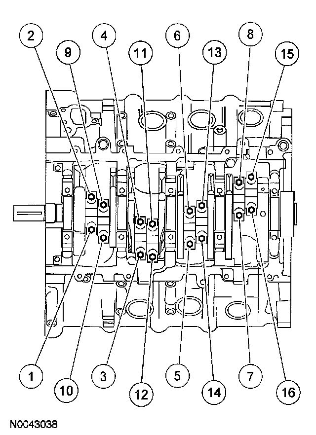
Stage 1: Tighten to 43 Nm (32 ft. lbs.).
Stage 2: Tighten an additional 105 degrees.
Main Bearing Cap
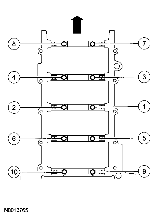
Tighten the vertical main bearing cap fasteners in the sequence shown, in 2 stages.
Stage 1: Tighten to 40 Nm (30 ft. lbs.).
Stage 2: Tighten an additional 90 degrees.
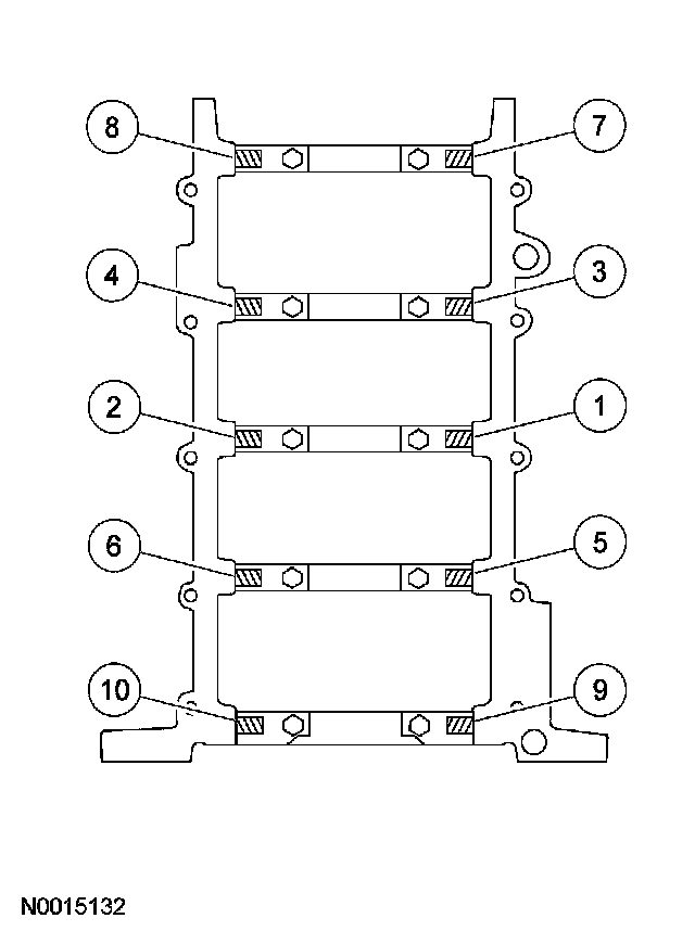
Tighten the jackscrews against the cylinder block in the sequence shown in 2 stages.
Stage 1: Tighten to 5 Nm (44 inch lbs.).
Stage 2: Tighten to 10 Nm (89 inch lbs.).
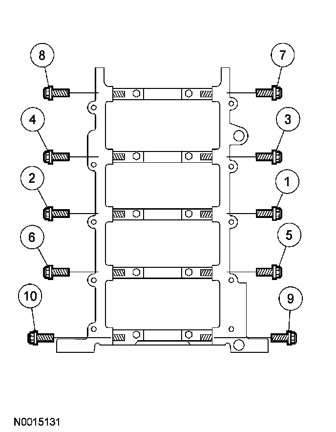
Install the side bolts and tighten them in the sequence shown.
Tighten to 21 Nm (15 ft. lbs.).