September 30: LEMON manuals is back up on a temporary server! Slowness is possible
Mini ISO Relay
- Remove mini ISO relay. Measure resistance between appropriate relay terminals. See MINI ISO RELAY RESISTANCE SPECIFICATIONS
table. See Fig 1
. If resistance is as specified, go to next step. If resistance is not as specified, replace relay.
MINI ISO RELAY RESISTANCE SPECIFICATIONS
| Between Terminals No. |
Resistance |
| 85 & 86 |
50-100 Ohms |
| 30 & 87a |
5 Ohms Or Less |
| 30 & 87 |
Greater Than 10 K/Ohms |
| 30 & 86 |
Greater Than 10 K/Ohms |
| 86 & 87a |
Greater Than 10 K/Ohms |
| 86 & 87 |
Greater Than 10 K/Ohms |
- Using a fused jumper wire, connect positive battery voltage to terminal No. 85. Using another jumper wire, ground terminal No. 86. Resistance should now be 5 ohms or less between terminals No. 30 and 87 and greater than 10 k/ohms between terminals 30 and 87a. If resistance is as specified, relay is okay at this time. If resistance is not as specified, replace horn relay.
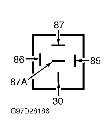 Courtesy of FORD MOTOR CO.