September 30: LEMON manuals is back up on a temporary server! Slowness is possible
No Start Test No 13 - Checking System Power Supply Circuits
- Turn ignition off. Disconnect TPS connector. Turn ignition on. Connect a voltmeter to Violet/White wire at TPS sensor connector and ground. If voltmeter is reading at least 4.5 volts, go to next step. If voltmeter is reading zero volts, go to step 3).
- Turn ignition off. Disconnect 60-pin connector from SMEC. Connect one lead of an ohmmeter to system ground eyelet. Touch other lead to cavities No. 15 and 16 of 60-pin connector. If ohmmeter is reading continuity with less than .5 ohm of resistance in both wires, replace SMEC for a bad logic board. If ohmmeter is not reading continuity on both wires, repair Black wire to ground for an open circuit to wiring harness splice and replace SMEC. If ohmmeter is reading more than .5 ohm of resistance at one or both wires, repair Lt. Blue/Red wires for high resistance to ground eyelet.
- Disconnect MAP sensor connector. Touch voltmeter positive lead to Violet/White wire at TPS sensor connector. If voltmeter is reading at least 4.5 volts, replace MAP sensor. If voltmeter is reading zero volts, go to next step.
- Turn ignition off. Disconnect 60-pin connector from SMEC. Connect voltmeter negative lead to ground. Turn ignition on. Touch positive lead of voltmeter to Orange wire in cavity No. 52 of 60-pin connector. If voltmeter reading is at least 8 volts, replace SMEC for a bad logic board. Before replacing SMEC, ensure cavity No. 52 is not damaged causing a poor connection. If voltmeter is reading zero volts, go to next step.
- Disconnect distributor pick-up harness connector. Connect positive lead of voltmeter to Orange wire in cavity No. 52 of 60-pin connector. If voltmeter is reading at least 8 volts, replace distributor pick-up. If voltmeter is reading zero volts, go to next step.
- Turn ignition off. Connect an ohmmeter lead to cavity No. 52. Connect other lead to Orange wire of distributor harness connector. If ohmmeter is reading continuity, go to next step. If ohmmeter is not reading continuity, repair Orange wire of cavity No. 52 for an open circuit to wiring harness splice.
- Disconnect 14-pin connector from SMEC. Connect a voltmeter negative lead to ground. Turn ignition on. Connect positive lead of voltmeter to Dk. Blue wire in cavity No. 4 of 14-pin connector. If voltmeter is reading within one volt of battery voltage, go to next step. If voltmeter is not reading within one volt of battery voltage, repair Dk. Blue wire in cavity No. 4 for an open circuit to wiring harness splice.
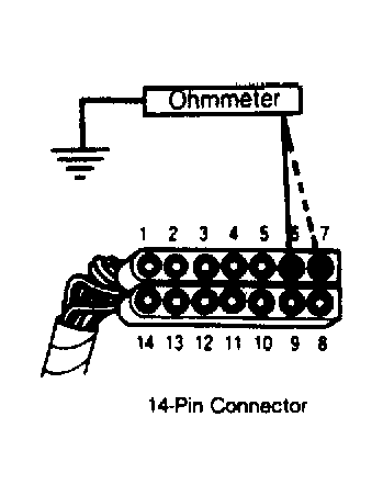
- Turn ignition off. Connect an ohmmeter lead to system ground eyelet. Connect other lead to cavities No. 6 and 7 of 14-pin connector. If ohmmeter is reading continuity at both cavities with less than .5 ohm of resistance, replace SMEC for a bad power board. Before replacing SMEC, ensure cavities No. 6 and 7 are not damaged causing a poor connection. If ohmmeter is not reading continuity at either cavity, repair Black wires of cavities No. 6 and 7 for an open circuit to wiring harness splice and replace SMEC. If ohmmeter is reading continuity with less than .5 ohm of resistance, repair Black wire from ground eyelet to ground for high resistance.