September 30: LEMON manuals is back up on a temporary server! Slowness is possible
Ecu Input Signals
- Timing control and triggering of the fuel injectors are based on input signals from the TDC/CRANK/CYL sensors. These sensors are simple Permanent Magnet (PM) generator pick-up coils.
- Using a DVOM (preferably with bar-graph function) on low-volt scale, check each sensor for pulse voltage signal at indicated ECU harness terminals with engine cranking. See ECU INPUT SIGNAL & RESISTANCE TEST TERMINALS table. If pulse signal is present, sensor is okay. If pulse signal is not present, go to next step.
- Ensure ignition is off. Check wiring connections. Check resistance of each sensor at indicated ECU harness terminals. See ECU INPUT SIGNAL & RESISTANCE TEST TERMINALS table. If resistance is not within specification, go to step 5). If resistance is within specification, go to next step.
ECU INPUT SIGNAL & RESISTANCE TEST TERMINALS
| Application |
ECU Terminals |
Resistance |
| Integra |
| CRANK |
B10 & B12 |
350-700 Ohms |
| CYL |
C1 & C2 |
350-700 Ohms |
| TDC |
C3 & C4 |
350-700 Ohms |
| Legend |
| CRANK No. 1 |
B15 & B16 |
600-950 Ohms |
| CRANK No. 2 |
B14 & B13 |
600-950 Ohms |
| CYL No. 1 |
B12 & B11 |
600-950 Ohms |
| CYL No. 2 |
B9 & B10 |
600-950 Ohms |
- Check continuity to ground on each terminal. If continuity exists, disconnect sensor connector, and recheck appropriate ECU terminal for continuity to ground. If continuity still exists, repair short to ground in harness. If continuity does not exist, replace sensor assembly.
- Disconnect sensor connector at sensor. See Fig 1 and Fig 2
. Check resistance of sensor. See ECU INPUT SIGNAL & RESISTANCE TEST TERMINALS tables. If resistance is within specification, repair open, short or corrosion in sensor harness between ECU and sensor. If sensor resistance is not within specification, replace sensor assembly.
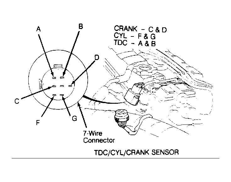 Courtesy of AMERICAN HONDA MOTOR CO., INC.
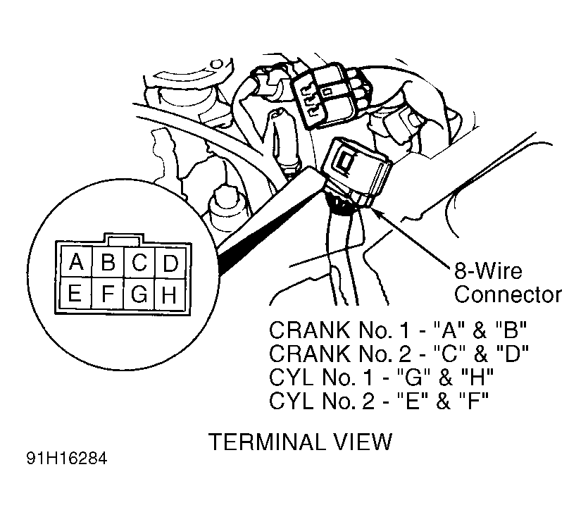 Courtesy of AMERICAN HONDA MOTOR CO., INC.