P1610
DTC P1610 Main Relay Circuit High VoltageWiring Diagram:
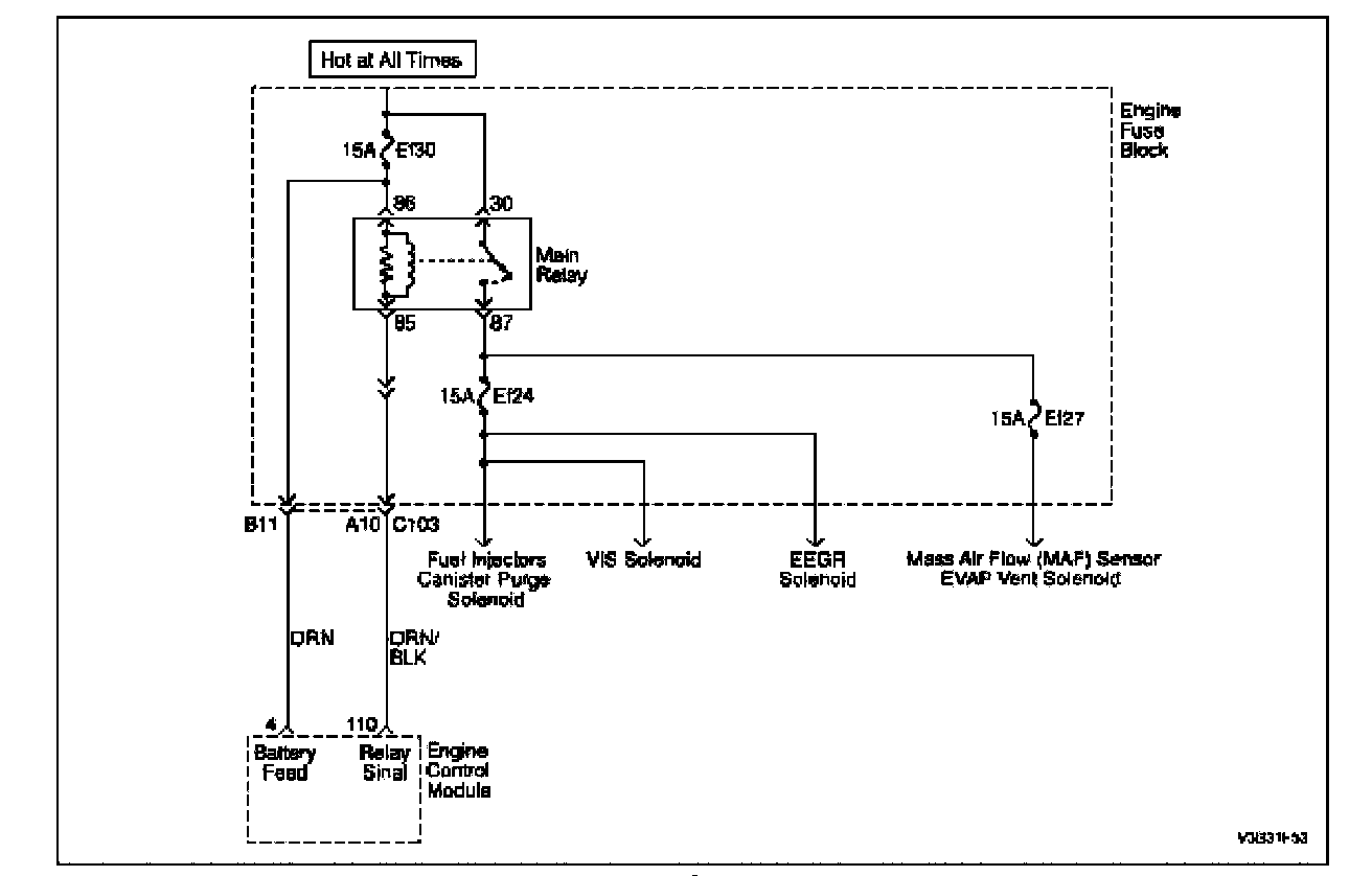
Circuit Description
When the ignition switch to ON, main relay will grounded to ECM internal ground by ECM controlling.
A system voltage DTC will set whenever the voltage is below a calibrated value.
Conditions for Setting the DTC
- The main relay circuit is a short to battery condition exists.
- Ignition ON.
Action Taken When the DTCs Sets
- The Malfunction Indicator Lamp (MIL) will not illuminate.
- The ECM will record operating conditions at the time the diagnostic fails. This information will be stored in the Freeze Frame and Failure Records buffers.
- A history DTC is stored.
Conditions for Clearing the MIL/DTC
- A history DTC will clear after 40 warm up cycles without a fault.
- Using the scan tool can clear DTC(s).
Diagnostic Aids
Inspect harness connectors for backed-out terminals, improper mating, broken locks, improperly formed or damaged terminals, and poor terminal-to-wire connection at the ECM. Inspect the wiring harness for damage. If the harness appears to be OK, observe the A/C pressure display on the scan tool while moving the connectors and wiring harnesses related to the ACP sensor. A change in the A/C pressure display will indicate the location of the fault.
If DTC P1610 cannot be duplicated, reviewing the Fail Records vehicle mileage since the diagnostic test last failed may help determine how often the condition that caused the DTC to set occurs. This may assist in diagnosing the condition.
Step 1 - 8:
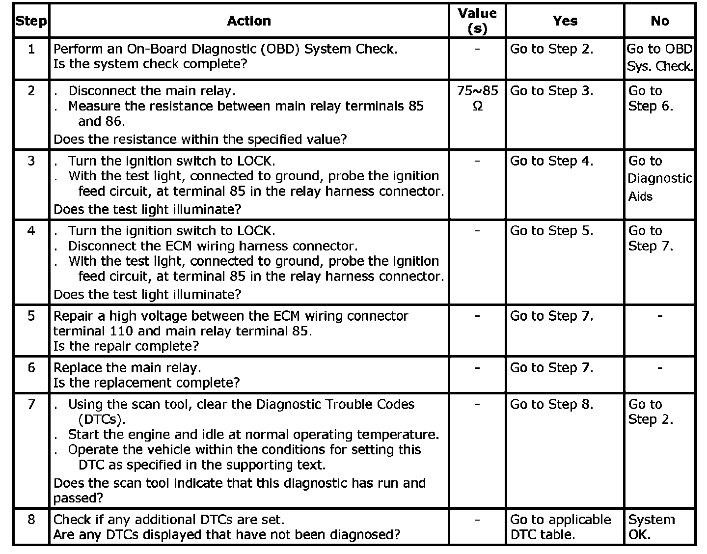
DTC P1610 - Main Relay Circuit High Voltage