P1504
DTC P1504 Vehicle Speed Sensor CAN MalfunctionWiring Diagram:
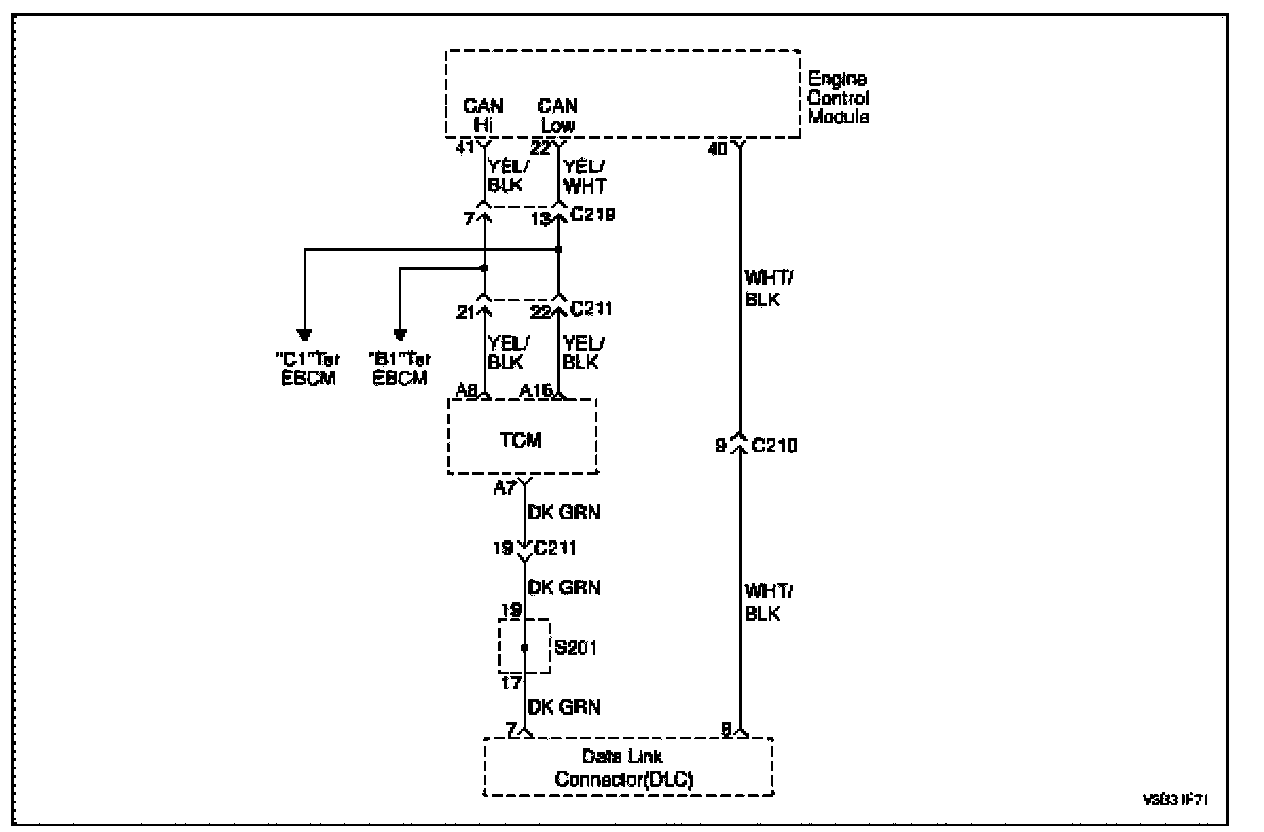
Circuit Description
Information transmit between the Transmission Control Module (TCM) and the Engine Control Module (ECM) through the CAN line.
- Engine malfunction signal.
- Engine speed.
- Engine output torque reduction signal.
- Engine coolant temperature.
- Vehicle speed signal.
Conditions for Setting the DTC
- The TCM message missing on the CAN bus (DTC P1671) or CAN bus off (DTC P1672) or emit error on the Can bus (DTC P1673).
- The debaunce of the failure is done in on step as soon as VS run.
Action Taken When the DTC Sets
- The Malfunction Indicator Lamp (MIL) will illuminate.
- The ECM will record operating conditions at the time the diagnostic fails. The information will be stored in the freeze frame and failure records buffers.
- A history DTC is stored.
Conditions for Clearing the MIL/DTC
- The MIL will turn off at the end of 3 consecutive ignition cycles in which the diagnostic runs without a fault.
- A history DTC will clear after 40 warm up cycles without a fault.
- DTC(s) can be cleared by using the scan tool.
Diagnostic Aids
An Intermittent problem may be caused by a poor connection, rubbed through wire insulation, or wire that is broken inside the insulation.
Any circuitry, that is suspected as causing the complaint, should be thoroughly checked for the following conditions.
- Backed-out terminals.
- Improper mating.
- Broken locks.
- Improperly formed.
- Damaged terminals.
- Poor terminals to wire connection.
- Physical damage to the wiring harness.
Step 1 - 6:
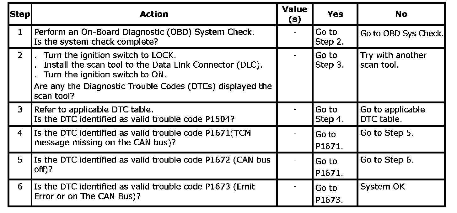
DTC P1504 - Vehicle Speed Sensor CAN Malfunction