P0265
DTC P0265 Injector 2 High InputWiring Diagram:
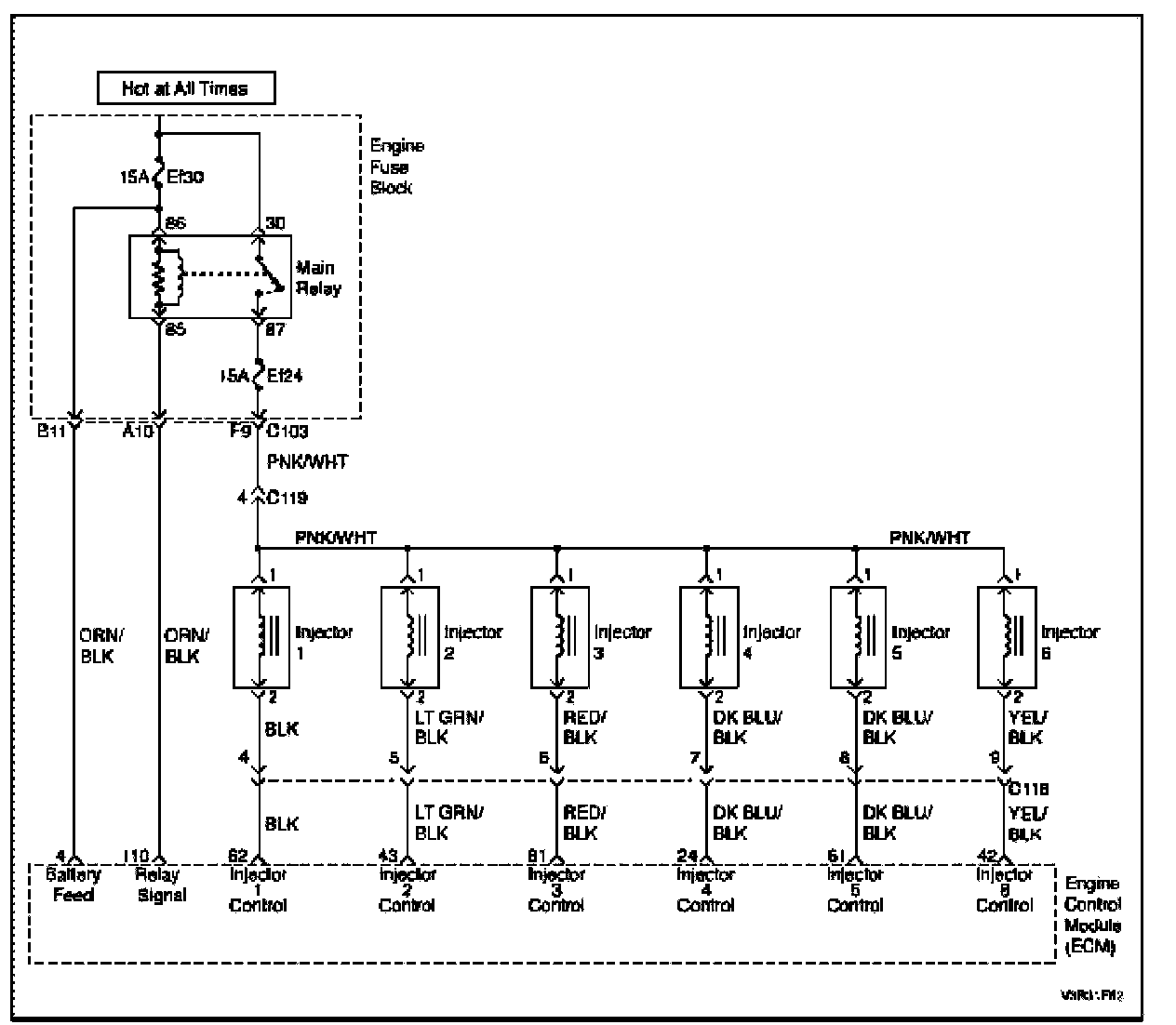
Circuit Description
The engine control module (ECM) has six individual injector driver circuits, each of which controls an injector. When a driver circuit is grounded by the ECM, the injector is activated. The ECM monitors the current in each driver circuit. The ECM measures a voltage drop through a fixed resistor and controls it. The voltage on each driver is monitored to detect a fault. If the voltage is not what the ECM expects to monitor on the circuit, a DTC is set. This DTC detects a high voltage and/or a short to battery voltage conditions.
Conditions for Setting the DTC
- A short to battery condition in the injector 2 circuit exists.
Action Taken When the DTC Sets
- The Malfunction Indicator Lamp (MIL) will illuminate.
- The ECM will record operating conditions at the time the diagnostic fails. This information will be stored in the Freeze Frame and Failure Records buffers.
- A history DTC is stored.
Conditions for Clearing the MIL/DTC
- The MIL will turn off at the end of three (3) consecutive validation cycles in which the diagnostic runs without a fault.
- A history DTC will clear after 40 warm up cycles without a fault.
- DTC(s) can be cleared by using the scan tool.
Diagnostic Aids
An injector driver circuit that is open or shorted to voltage will causes a DTC P0265 to set. It will also cause a misfire due to an inoperative injector. A misfire DTC should also be set indicating which injector is inoperative.
Long-term and short-term fuel trims that are excessively high or low are a good indication of an injector malfunctioning. Refer to Fuel Injector Balance Test to check for malfunctioning injectors.
Step 1 - 7:
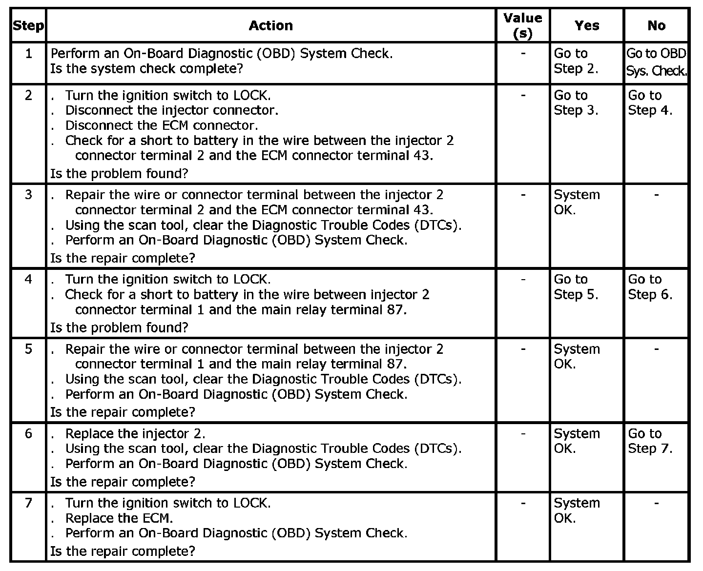
DTC P0265 - Injector 2 High Input