P0334
DTC P0334 Knock Sensor 2 MalfunctionWiring Diagram:
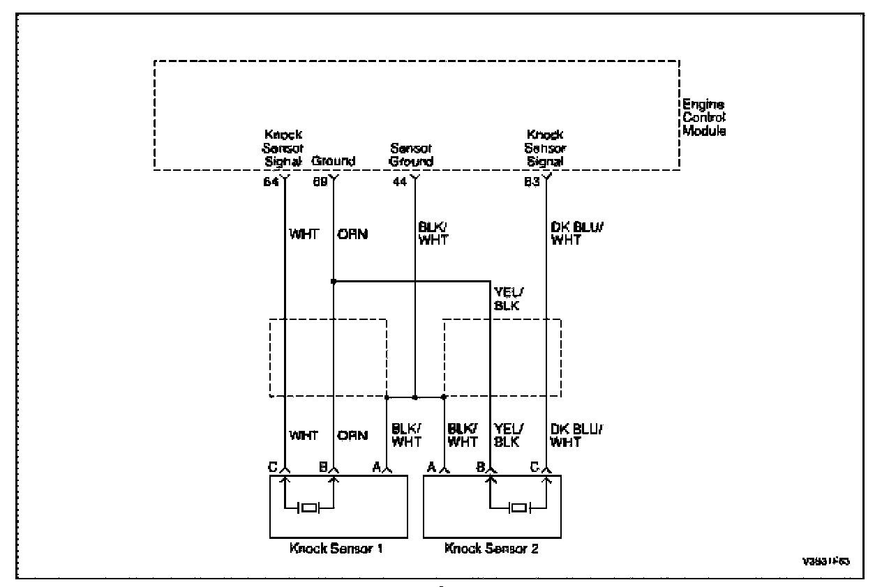
Circuit Description
The knock sensor (KS) system enables the engine control module (ECM) to control the ignition timing for the best possible performance while protecting the engine from potentially damaging levels of detonation. The knock sensor (KS) is located on the intake side of the engine block. The KS produces an AC voltage signal that varies depending on the vibration level during engine operation. The ECM adjusts the spark timing based on the amplitude and frequency of the KS signal. The ECM receives the KS signal through a signal circuit. The KS ground is supplied by the ECM through a low reference circuit. The ECM uses the KS signal to calculate the average voltage and then assigns a voltage range value. The ECM should monitor a normal KS signal within the voltage range. If the ECM detects the KS signal outside of the voltage range, or the KS signal is not present, this DTC sets.
Conditions for Setting the DTC
- The engine coolant temperature is higher than 60 °C (145 °F).
- The engine speed is higher than 1,400 rpm.
- The mass air flow is higher than 250 mg/stroke.
- No relevant DTCs are set.
- The knock sensor SPI bus failure during 5 seconds, and/or, the knock sensor voltage reading is less than 0.1 V, and/or, the difference between a original signal value and filtering value is less than 5%.
Action Taken When the DTC Sets
- The Malfunction Indicator Lamp (MIL) will illuminate.
- The ECM will record operating conditions at the time the diagnostic fail. This information will be stored in the Freeze Frame and Failure Records buffers.
- A history DTC is stored.
Conditions for Clearing the MIL/DTC
- The MIL will turn off at the end of three (3) consecutive validation cycles in which the diagnostic runs without a fault.
- A history DTC will clear after 40 warm up cycles without a fault.
- DTC(s) can be cleared by using the scan tool.
Diagnostic Aids
Check and correct any abnormal engine noise before using the diagnostic table.
Any circuitry that is suspected as causing engine noise complaint should be thoroughly checked for the following conditions:
- Backed-out terminals
- Improper mating
- Broken locks
- Improperly formed
- Damaged terminals
- Poor terminal-to-wire connection
- Physical damage to the wiring harness
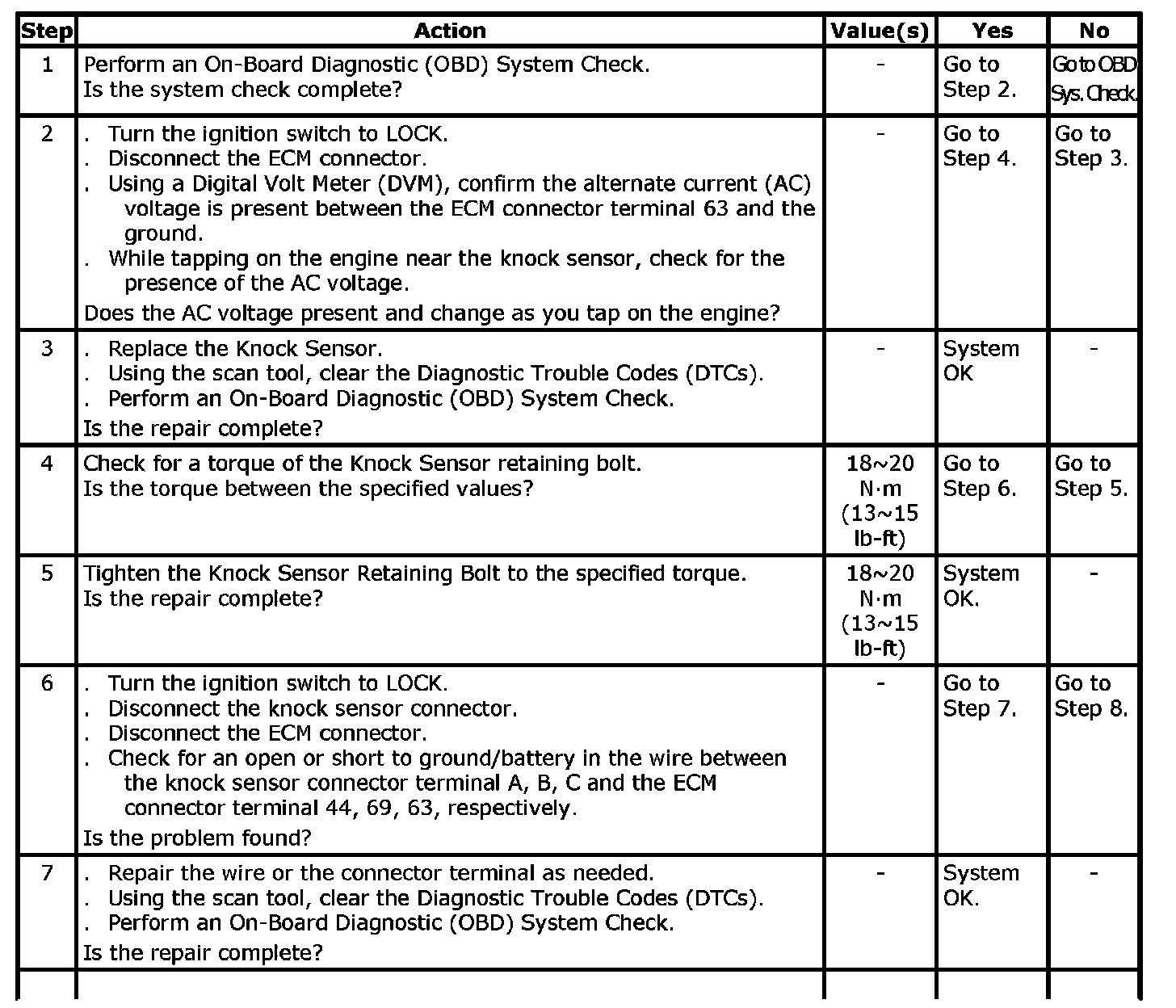
Step 1 - 7:
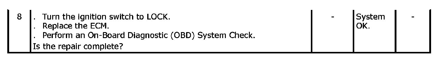
Step 8:
DTC P0334 - Knock Sensor 2 Malfunction