Oxygen Sensor Heater For O2 Sensors Before (TWC), Checking
Components, checking
Oxygen sensor heater for oxygen sensors before Three Way Catalytic Converter (TWC), checking
NOTE: When servicing terminals in harness connector of oxygen sensors, use only gold-plated terminals.
Recommended special tools and equipment
- VAG1526 multimeter or VAG1715 multimeter
- VAG1594 connector test kit
- Wiring diagram
Test requirements
The respective fuses of Heated Oxygen Sensor (HO2S) -G39- and Heated Oxygen Sensor (HO2S) 2 -G108- must be OK.
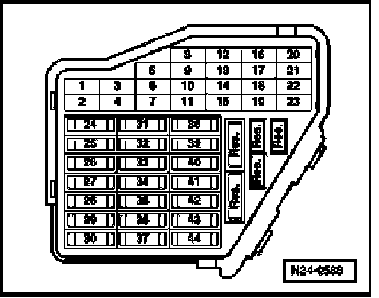
- Fuses -1, 2, 3, 4 and 7- in protective housing (plenum chamber, left) must be OK:
- Battery voltage must be at least 11.5 Volts.
- All electrical consumers such as, for example, lights and rear window defroster must be switched off.
- Parking brake must be engaged or else daylight driving lights will be switched on.
- For vehicles with automatic transmission, selector lever must be in position -P-or -N-.
- If vehicle is equipped with an A/C system, it must be switched off.
- Ground (GND) connections between engine and chassis must be OK.
Test sequence
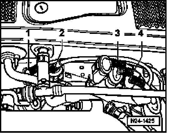
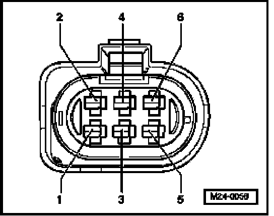
- Disconnect 6-pin harness connector to the respective oxygen sensor:
- Heated Oxygen Sensor (HO2S) -G39-, bank 1 6-pin harness connector (black) -1-,
- Heated Oxygen Sensor (HO2S) 2 -G108-, bank 2 6-pin harness connector (brown) -2-.
NOTE:
- Bank 1 = Cylinder bank 1, in direction of travel, right
- Bank 2 = Cylinder bank 2, in direction of travel, left
Checking voltage supply and wiring to control module
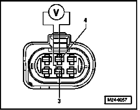
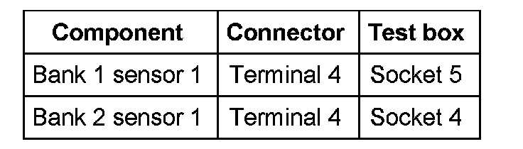
- Connect multimeter to terminals 3 + 4 of connector to Engine Control Module (ECM) for voltage measurement.
- Start engine, and let run at idle.
Specified value: at least 7.0 V
If specified value is obtained:
- Switch ignition off.
- Erase DTC memory of Engine Control Module (ECM), Diagnostic mode 4: Reset/erase diagnostic data.
- Generate readiness code. Monitors, Trips, Drive Cycles and Readiness Codes
If specified value is not obtained:
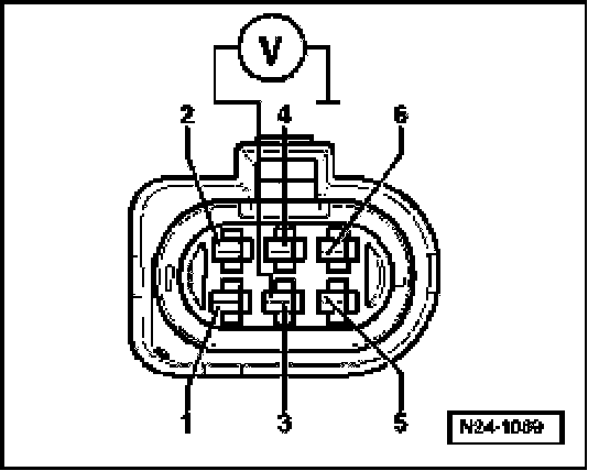
- Connect multimeter to terminal 3 of connector to Engine Control Module (ECM) + Ground (GND) for voltage measurement.
Specified value: at least 11.0 V
- Switch ignition off.
If specified value is not obtained:
- Check voltage supply at 6-pin connector terminal 3 according to wiring diagram.
- Erase DTC memory of Engine Control Module (ECM), Diagnostic mode 4: Reset/erase diagnostic data.
- Generate readiness code. Monitors, Trips, Drive Cycles and Readiness Codes
If specified value is obtained:
- Check Ground (GND) activation of the respective oxygen sensor heater.
- Connect test box to control module wiring harness, connect test box for wiring test. Test Box, Connecting For Wiring Test
- Check wires between test box and 6-pin connector to Engine Control Module (ECM) for open circuit according to wiring diagram.
Wire resistance: max. 1.5 Ohms
- Also check wires for short circuit to B+ and Ground (GND).
Specified value: Infinity Ohms
- Erase DTC memory of Engine Control Module (ECM), Diagnostic mode 4: Reset/erase diagnostic data.
- Generate readiness code. Monitors, Trips, Drive Cycles and Readiness Codes
If no malfunctions are found in wires:
- Replace Motronic Engine Control Module (ECM) -J220-.